A cutting tool is a wedge shape device that removes material from blanks to give it a size and shape. In the single point Cutting tool, there is only a single point of contact between the tool and the workpiece. So let’s learn more about Single Point Cutting Tool in this article.
How does Cutting Tool work?
While machining or cutting operation, the cutting tool compresses a thin layer of metal around it and eventually shear it off when the pressure becomes excessive.
To cut metals, three relative motions are required. Those are feed, velocity, and depth of cut. Though the cutting tool does not provide all these motions, the cutting tool is designed in such a shape that the machine can provide all those motions.
The size and shape of the machine tools largely depend on the operation that is intended. However, the basic principles remain the same.
Types of Cutting Tool
Based on how many surfaces or wedges of the tool has to touch against the workpiece, machine tools are divided into the following types.
- Single point Cutting tool
- Double point Cutting tool
- Multi point Cutting tool
Single Point Cutting Tool Definition
As the name suggests, single point Cutting tool has a single wedge that touches the workpiece and removes metals. Single point cutting tools are used for various operations like turning, facing, etc in machines like lathe, planer, shaper machines.
Please make a note that even a single point cutting tool may have more than one wedge but only one wedge touch the workpiece per shot. If there two wedges touching the workpiece per shot then it is called a double point Cutting tool and if there are multiple wedges touching at a time then it is called multi point Cutting tool.
The point of the single point Cutting tool is bounded by the face along which the chips travel through after the tools remove the metal chips.
Single Point Cutting Tool Nomenclature
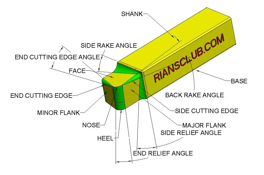
We will talk about different single point Cutting tool nomenclature based on their geometry and different angles. Here is the nomenclature of the different areas of a single point Cutting tool.

- Shank
- Flank
- Face
- Heel
- Nose
- Cutting edge
Shank
This is the main body of the tool. The shank is used to hold the tool.
Flank
The surface adjacent to the cutting edge is called flank.
Face
The face is the area along which the metal chips slides out after cutting operation.
Heel
This area is the intersection between flank and the base of the tool
Nose
This is the area where the side cutting edge and the end cutting edge meets.
Cutting edge
This is the area that actually cuts the metal. Cutting edge consists of side cutting edge, end cutting edge and the nose.
Here are the different angles that are available in a cutting tool geometry
- Side cutting edge angle
- End cutting edge angle
- Side relief angle
- End relief angle
- Back rack angle
- Side rack angle
Side cutting edge angle
The angle between the side cutting edge and the side of the tool is called the site cutting edge angle. This is also called the lead angle.
End Cutting Edge Angle
This is the angle between the end cutting edge and a line perpendicular to the tool shank.
Side Relief Angle
The angle between the portion of the side flank immediately after The side cutting edge and a line perpendicular to the base of the tool.
End Relief Angle
The angle between the portion of the end flank immediately after the end cutting edge and a line perpendicular to the base of the tool.
Back Rack Angle
The back rack angle is the inclination of the face towards or away from the end cutting edge. If the inclination is downwards towards the end cutting edge, then the back rake angle is negative, and if the inclination is upwards from the end cutting edge, then the back rake angle is positive.
Side Rake Angle
The side rack angle is the inclination towards or away from the side cutting edge. If the inclination is towards the side cutting edge, then the angle value is negative, but if the inclination is away from the side cutting edge, it’s positive.
Single Point Cutting Tool Material
Here are the materials that is widely used in single point cutting tool
- High carbon steel
- Ceramics
- Diamonds
- High-speed steel
- Cemented carbide
- Cubic boron nitride (CBN)
Single Point Cutting Tool Application
Here are the machines or operations where single point cutting tool is mainly used.
- Shaper Machine
- Planner Machine
- Lathe Machine
Single Point Cutting Tool Advantages
- Simple in design
- Easy to manufacture
- Relatively cheap compared to other types of tool
- A wide variety of operations can be performed
Single Point Cutting Tool Disadvantages
- The low material removal rate
- Less productive and can not be used for mass production
- High wear rate
- Short tool life
- High Cutting temperature
Conclusion : Single Point Cutting Tool
That’s all we have in this article. I hope that you all got a fair idea of a single-point cutting tool and various terminology used in its geometry.
It is a perfect tool for the tool shop, but it is not widely used in mass production due to its limitations. I hope all your questions on the single-point cutting tool are cleared by now. If you still have any questions or queries, please write in the comment section, and I will be happy to help.
You may also like to read: What is abrasive jet machining
Frequently Asked Questions ( FAQ) On Single Point Cutting Tool
What is Single Point Cutting Tool?
It is a tool that has one surface contact with the workpiece to remove metal chip.
Is Drill bit Single Point?
No. Drill bit does not comes under single point cutting tool
What are key nomenclatures used in the Single Point Cutting tool?
Shank
Flank
Face
Heel
Nose
What are key angle nomenclatures used in the Single Point Cutting tool?
Side cutting edge angle
End cutting edge angle
Side relief angle
End relief angle
Back rack angle
Side rack angle


