Do you know that nowadays almost all mechanical design work is done on computers? You can, in fact, build a digital mock-up on a computer. The introduction of computers in mechanical design has brought a revolution. That’s why the term CAD CAM CAE became so popular. So let us learn in this article more about what is CAD CAM CAE and what the difference is between CAD CAM CAE.
Following abbreviations will be used throughout this article. So it makes sense to mention those at the beginning of this article.
- CAD: Computer-Aided Design
- CAM: Computer-Aided Manufacturing
- CAE: Computer-Aided Engineering
What is CAD ( Computer Aided Design)
CAD means computer-aided design, Design with the help of a computer. CAD is a generic term used to specify a design that was done on computers.
There are many software packages in the market for CAD. Those software help engineers to create three-dimensional objects and parametric two-dimensional drawings. No manual interface. Each and everything is done on computers.
If you change any 3D models built using CAD software, the associated drawing also gets updated. Can you ever think of this in manual drafting? Basically, CAD has replaced all manual drafting practice and automated the design work.
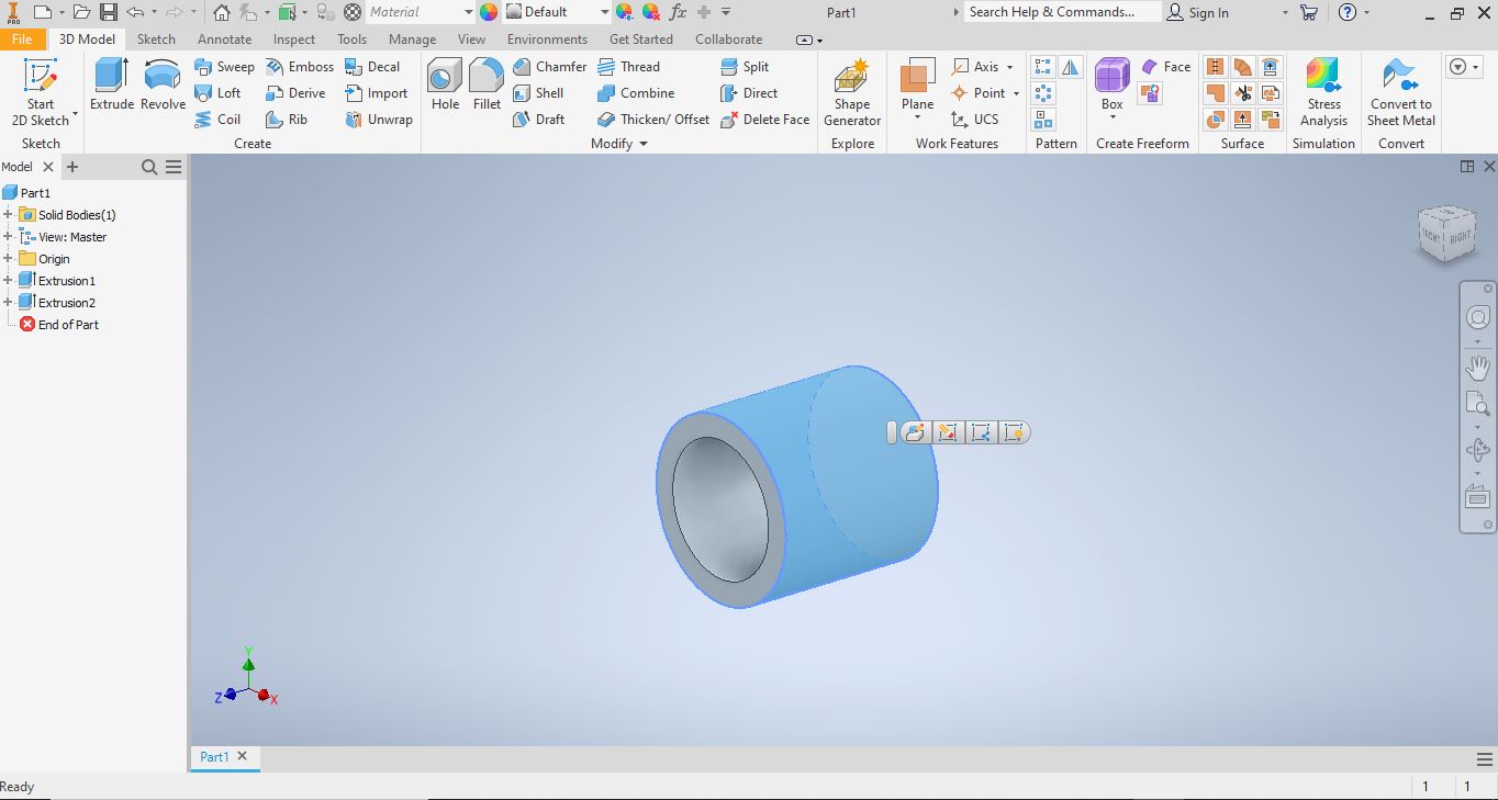
Do you know that you can also create a 3D CAD assembly of components in CAD? It is a kind of virtual mock-up of an actual product. You can visually see how your actual product will look like even before you physically manufacture it. Does not it sound great?
You cal also check parts for interference and fix those on the fly. You can add mechanism constraints and animate parts to see how parts behave in motion.
These are just a very few capabilities of CAD, I can say its just about 10%. It takes more than a year to learn any CAD software. So you can imagine how vast CAD capabilities are.
You may like to read: 30 best mechanical engineering blog
Types Of CAD
There are two types of CAD ( Computer aided design) package available in the market
- Two dimensional CAD
- Three dimensional CAD
Two dimensional CAD
In two dimensional CAD, you can only see the X and Y axis of an object. Separate views are required to observe the Z-axis. Two dimensional CAD is almost obsolete nowadays except for fields like civil engineering and architectural engineering
Three dimensional CAD
In three-dimensional CAD, you will be able to see all X, Y, and Z-axis in a single view. Three-dimensional CAD gives the most realistic look of the actual object. 99% of mechanical designs have now adopted three dimensional CAD practice.


Popular CAD software Modules
There are hundreds of modules in a CAD software package. But below are few modules which are widely used in industries
- Part modeling
- Surface modelling
- Sheet metal modelling
- Assembly
- Drafting
- Mechanism
- Simulation
- Animation
- Welding
- Harness routing
Popular CAD software list
Must Read : Best free CAD software list
Why computer aided design ( CAD) is required?
Before 1980, engineers used to do manual drafting. Those used to take a lot of time and correcting errors was a big challenge. On top of that, if there was a design change, all drafting needs to be done again.
Since manual drafting was a time-consuming task, the overall design cycle time was too long. That is why computer-aided design came into practice.
CAD made designers’ life very simple. Drafting got much faster and making changes got very quick. Even if there a big design change, the drafting change became very quick with CAD software.
Due to CAD, the overall design cycle time also got reduced. This helped industries to lunch products quickly and outcome their competitor.
Advantages of CAD Softwares
- Reduce design cycle time
- Reduce design iteration time
- Reduce error correction time
- A realistic 3D model can be created
- A virtual mock-up can be created
- Real-time interface detection is possible
- Parametric 2D drawing can be created
- Drafting is very easy and quick
Disadvantages of CAD software
- Dynamic analysis is not possible
- Product flexibility is not available
- Real-time simulation is not possible ( Special Module is required)
You may like to read: What are the differences between Creo and SolidWorks
What Is CAM ( Computer Aided Manufacturing)
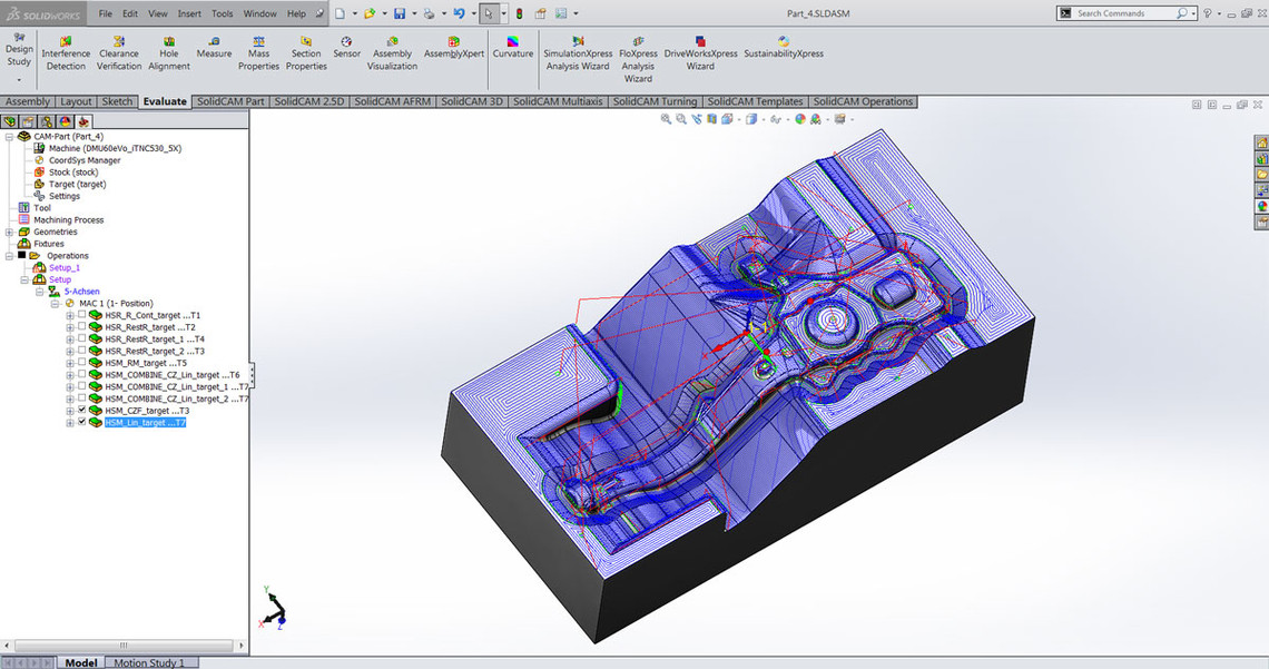
CAD helps to visualize a design and shows how it may function. CAM helps to decide how to make that CAD part physically. So basically, CAM software minimizes the gap between CAD and manufacturing. It acts as a bridge between CAD and manufacturing.
CAM software creates all required codes to run an NC or CNC machine. It helps to selects tools, decides a tool guide path, and other miscellaneous functions. You can feed those codes in a machine to make it perform
We all know that there are numerous types of machines. Not all CAM software can create codes for all machines. That is why there are different CAM software for different types of manufacturing operations.
How does CAM software work?
All CAM software needs 3D CAD models as input. Usually, all CAM software supports native CAD format files. If not, 3D models need to be exported to various neutral formats like Step or Iges before importing to any CAM software.
Once the CAD file is imported, the CAM software validates the data for manufacturability. Often the raw CAD data is not suitable for CAM. The CAM software fix all those manufacturability issues and prepare it for manufacturing
The CAM software then decides the tools that need to use, choose the tool path, decides when the coolant should be injected and all other function that the machine is going to perform.
Once all functions are defined, the CAM software creates the program for the CNC machine using G code and M code and other standards coding. The program is then fed into the machine.
Machines can read CAM programs very easily. The machine is then prepared based on the program and run all the function as specified in the program.
What CAM software does?
All CAM software typically does the following functions
- Error Checking
- Tool path generation
- Machine Configuration
- Machine optimization
Error Checking
As I said earlier, all CAM software checks manufacturability errors in CAD files. If any errors are found, CAM software fixes all those based on the available machines synchronized with that CAM software.
Tool path generation
Tool path generation is one of the key functions that CAM software does. Based on the available tool in the machine, the software creates the tool movement path using G codes, M codes, and other coding standards
Machine Configuration
Not only toolpath generation, but CAM software also decide which tool to use, how much to cut, at what angle the tool should hit, and numerous other functions. So basically the CAM software gives all configurable instruction to machines.
Machine optimization
CAD software helps to choose the best setting for a machine to perform at its best. If we operate the machine manually, it would have been very tough. Since all CAM software are synchronized with machines, so it can decide the best available resource in a machine
Popular CAM software list
Advantages of CAM software
- Prepare CAD models for manufacturing
- Creates tool path
- Acts as an interface of a machine
- Control all functions of machines
- Optimize the machine to give the best output.
What is CAE ( Computer aided engineering)
CAD software can not check how a 3D model will behave when forces or loads are applied. To check how those models behave under different loading conditions, you need to use CAE software.
CAE validates a design based on real-life constraints. It tells engineers about the robustness of a design and at what condition it may fail. Basically, all CAE software checks if the design will perform or not if you decide to manufacture that part.
CAE software can also check how the part will perform in different thermal condition. You can also check fluid flow using CAE software.
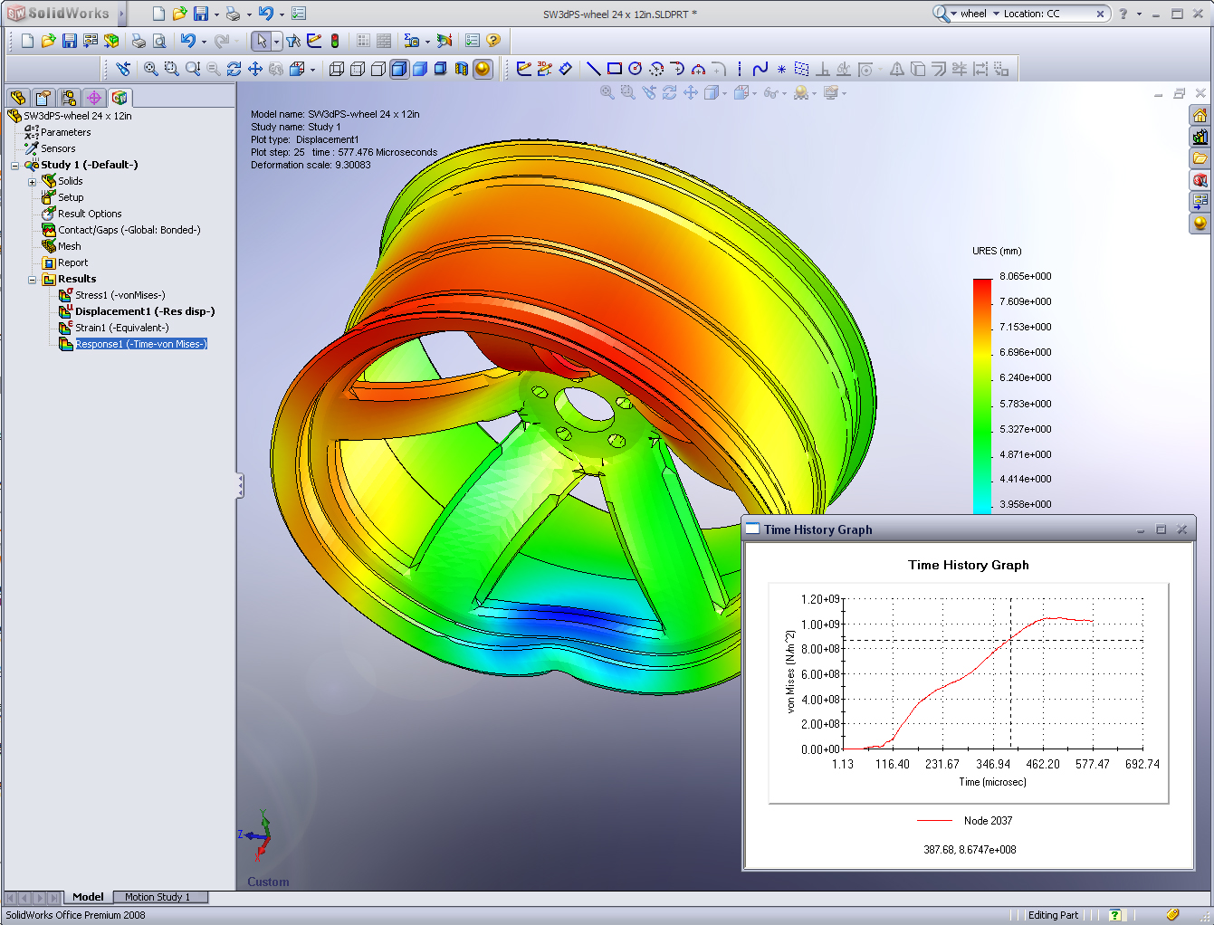
Computer Aided Engineering fields
Below are few important field under computer aided Engineering
- FEA: Finite element analysis ( To check Stress)
- CFD: Computational fluid dynamics ( to check thermal and fluid flow)
- Multibody dynamics ( MBD) or kinematics
The workflow of CAE software
- Pre-processing
- Analysis
- Post-processing
Polular CAE software list
Advantages of CAE software
- Real-time analysis can be done.
- Failure more can be investigated
- Thermal analysis is possible
- Fluid flow analysis can be done
Difference between CAD CAM CAE
| CAD | CAM | CAE |
|---|---|---|
| Maibly used for creating 3D model and drawing | Mainly used for creating NC and CNC code | Mainly used for analysing parts |
| Used for product design | Used for product manufacturing | Used for Product analysis |
| CAD is independent of CAD and CAE | CAM uses CAD file as input | CAE uses CAD file for analysis |
| Virtual mock up design is possible | No way to build virtual mock up | No option |
| Easiest to learn and implement | Fair amount of manufacturing knowledge is required | Steep learning curve |
Conclusion
CAD CAM CAE brought a revolution to the engineering industry and this is the future. Hardly there are any industries that don’t use CAD CAM CAE which automated the full product life cycle.
I hope you all got a brief idea about CAD CAD and CAE. This field is vast. Typically an engineer takes more than a year to learn CAD CAM or CAE software. So you can understand the versatility of this software.
If you do have any questions, please write in the comment section and I will be happy to assist you.
Frequently Asked Questions
What is CAD
CAD is a group of softwares used in 3D modelling and 2D drafting
What is CAM
CAM is a group of software used to create codes and assist in manufacturing
What is CAE
CAE is a group of software used for analyzing designs created using CAD software
