Dimensioning plays a key important role in engineering drawing. Without proper dimensioning, it is next to impossible to convey the design intent to the cross-functional team. So in this article, we will learn about, dimensioning, types of dimensioning, dimensioning systems, and dimensioning principles.
What is Dimensioning?
A dimension is a numerical value that expresses the size, location, orientation, form, or any other geometric properties of a component in the appropriate units of measurement.
The process of measuring an object’s area or volume is known as dimensions. It is a method of calculating capacity for goods storage, handling, transportation, and billing.
An object can’t be built unless its dimensions and shape are known ahead of time. As a result, an engineering drawing depicting the object’s form, size, and other relevant details is required.
The dimensions serve as a reference for determining the relative sizes and locations of the object’s various components. An object’s size, the name of its parts, and the diameter of its hole are the primary uses of this tool.
Elements of Dimensioning:
Dimension Line:
Continuous, narrow lines are called dimension lines. Arrowheads denote the length of the line, which is drawn parallel to the surface.
Extension Line:
It’s a short line called a projection or extension line. To accurately size a surface, this line must be drawn perpendicular to that surface. Unlike the dimension line, the projection line extends slightly further.
Centre Line:
A line of this type is used to depict the center of a cylinder in a drawing.
Leader Line:
This line is used to write any note or specification on an object.
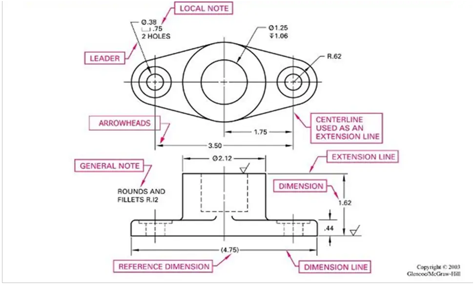
Arrow Head:
Arrowheads serve as visual cues for the line’s location dividing two dimensions. The arrowhead is usually required to have at least a 15° of angle. The arrowhead might be open, closed, or filled.
Numbers:
It is desirable to write down the shape of an object when it has been completed in geometric form. It is done with numbers. The number’s height is restricted to a minimum of three millimeters.
Types of Dimensioning
Here are the different types of dimensions that are used in engineering drawings.
1. Chain Dimensioning:
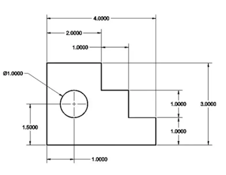
One way to dimension from one feature to the next is by using the chain dimensioning method. In addition, each length is measured starting at the end of the previous one. As a result, each dimension is dependent on the one before it.
The designer needs to remember that each dimension’s tolerance builds on the previous one when using this method.
Consequently, there is a buildup of tolerances or stacking, which can result in significant fabrication errors. Despite this flaw, this approach to design drawings is still widely used.
2. Parallel Dimensioning:
When numbers of dimensions are measured in the same direction from a common feature, i.e., the surface of the part, the method of indicating all the dimensions from the same feature is called parallel dimensioning. The dimension lines are equally spaced apart and parallel to one another.
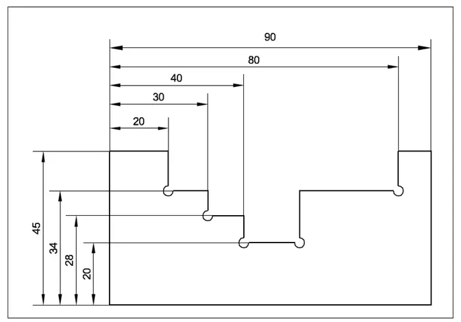
3. Progressive Dimensioning:
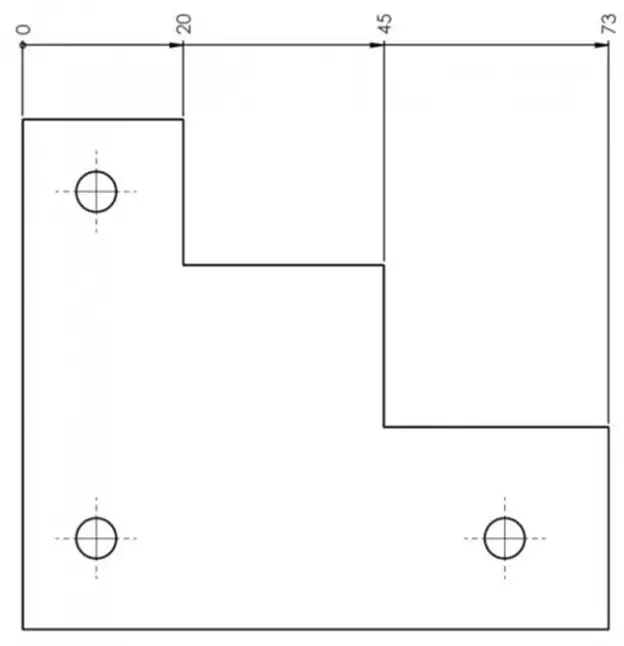
There are times when dimensioning from a specific datum is necessary. The common reference line shows the overall dimensions outside of the smaller dimensions.
4. Coordinate Dimensioning:
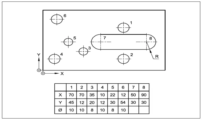
Other dimensioning styles can be replaced with coordinate table dimensions. When a part has a lot of dimensions, it can be easier to read if it is drawn in this style.
When drawing a plate with many holes, it’s best to use the coordinate system because using any other type of dimensioning would result in an unattractive drawing.
5. Combined Dimensioning:
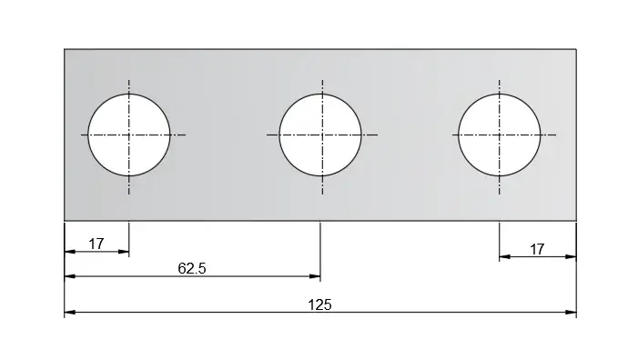
Chain dimensioning and parallel dimensioning are used in this method. When two or more similar features are combined, they form a new one.
6. Equidistant Dimensioning:
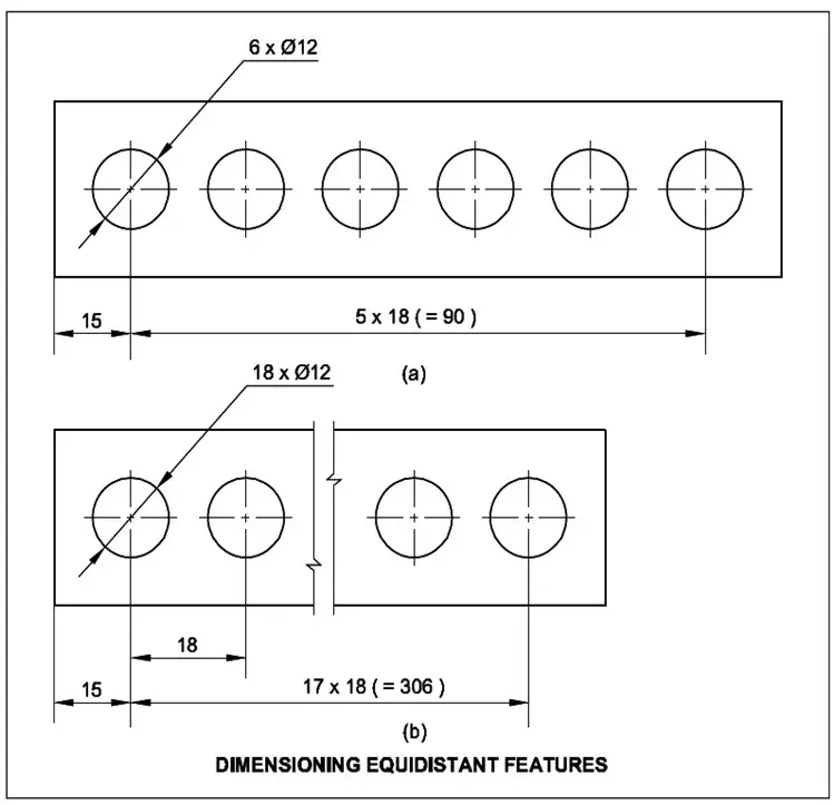
The intersection of the number of spacing and the dimension value simplifies the dimension. Each object in the stage set is equal in distance, so the distance between each point and the other objects in the stage set is called a median.
7. Repeated Dimensions:
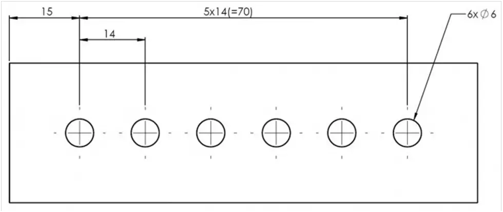
The product of multiple repeated features and the value of the dimension may only be indicated at one such feature when certain features or elements of the same size are repeated.
Dimension Systems
Aligned Dimensioning System:
The dimensions are shown perpendicular to the dimension lines in this system. In other words, when the drawing is viewed regularly, it is easy to see the horizontal dimensions. Similarly, vertical dimensions can be easily read using the right-hand side of the sheet.
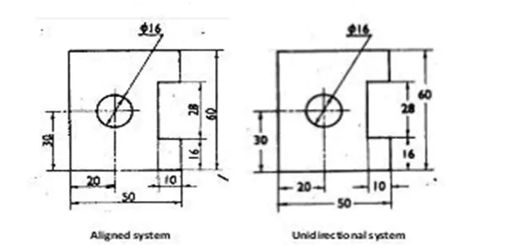
Unidirectional Dimensioning System:
As a result, when the drawing is viewed upright, the dimensions are shown in the vertical/upright position, making it easier to read. At the center of the dimension lines, the numerical values are listed.
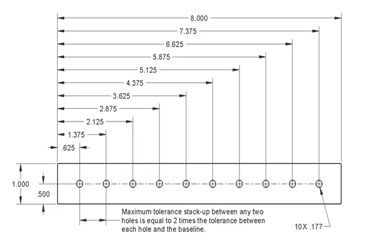
Base Line Dimensioning System:
In baseline dimensioning, a starting point for subsequent dimensions can be established. Dimension styles can be used to control the spacing between dimensions.
A Baseline dimension must be used in conjunction with an existing one. Using baseline dimensioning following a Linear dimension does not require you to identify the baseline origin.
Principle of Dimensioning
- Once a drawing has been completed, the measurements and comments on it must be written so that they can be easily seen. Adhere to the guidelines laid out specifically for this reason.
- A realistic representation of an object’s size and shape should be used when describing its dimensions. Ideally, measurements should be specified outside a scene, although they can be given inside if necessary.
- All dimensions are provided as a list of subgroups. Incorrect distribution has been made. A sensible way of expressing dimensions is required. Parallel to the object’s line, all dimensions should be written, and numerals should be written clearly.
- Repetition of dimensions should be avoided unless essential. Avoid adding unnecessary dimensions.
- The extension and dimension lines should never meet. In assigning dimensions to a drawing, it is important to remember that no unit should be written with a numerical value. Numbers must be easy to read and comprehend. The diameter of a circle, arc, or perfect, corresponds to the circle’s radius, arc, or perfect.
- Try sketching the concentric circles on the front view and then writing down their dimensions if necessary. The diameter of the circles should be visible if the dimensions of the circles are written using leader lines. Dimensions that are unclear or overly complicated should be avoided.
Conclusion: Types Of Dimensioning
Dimensions are highly significant in the engineering area. It is the most useful talent in an industry that will enable you to read any form of engineering drawing without any confusion. Learning and comprehending how dimensions are described is simple if you focus on learning.