GD&T ( Geometrical Dimensions And Tolerances ) is the new vocabulary of engineering drawings. This is the language that your drawings speak. How do they speak? Using some symbols. Let’s learn more about GD&T symbols with examples in this article.
At the end of this articles, there will be a link to download GD&T symbols PDF copy which you can use for your future reference.
It’s not a bad idea to have a rewind of what GD & T actually is. I know many of you are experts in GD&T, but setting the context of the article is important. Is it not?
What is GD & T?
Traditional drawings use linear dimensions, whereas modern drawings use Geometric dimensions and tolerances. There is a reason for that. The reason is the reduced part cost, less part rejection, and superior quality.
If you want to learn more about GD&T, then you should head over to the following category where I write about articles on GD & T
GD & T helps manufacturers with the design intent of the part. It also helps them find out which area of the part is more critical in form, fit, and function. They can take special care of those critical areas so that the part serves the purpose.
GD & T communicates the design intent through some symbols. Like how we have letters to make words and communicate with others, GD & T uses symbols to communicate with manufacturers and other state holders. So let’s dive in to explore GD & symbols with examples.
Looking for a job as a Mechanical Dimensional Control Engineer? Here are thousands of Vacancies For Mechanical Engineers On Jooble.
GD&T symbols with examples
Here is the summary of the key GD & T symbols used in engineering drawings. There are numerous other optional symbols used, which we show at the end of this article.

Here you can see that GD & T symbols are broadly categorized into the following categories based on their features. Each category is then further divided into a couple of types.
- Form
- Profile
- Orientation
- Location
- Run out
Form Tolerance
Form tolerance controls the shape of an object using different GD & T controls. Form tolerance symbols are classified into the following types.
- Straightness
- Flatness
- Circularity
- Cylindricity
Straightness
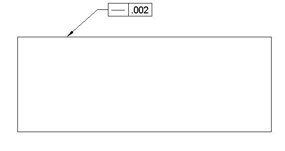
Straightness tolerance controls the form of individual features. It is used to control the straightness of a line element or a curve element on a surface. Every cross-section on that surface should have the same amount of straightness tolerance. Straightness tolerance does not need a datum.
Datum Required: No
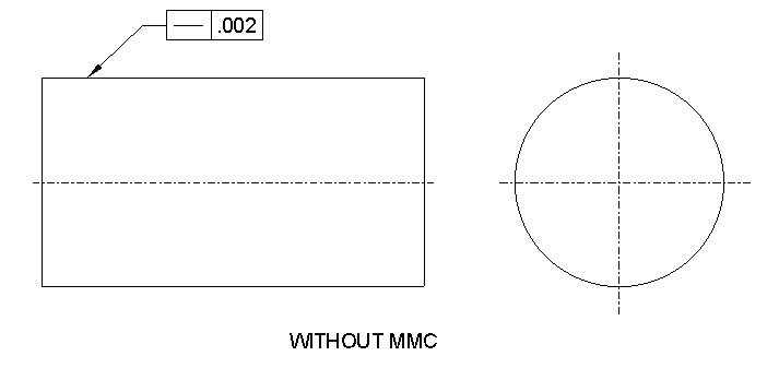
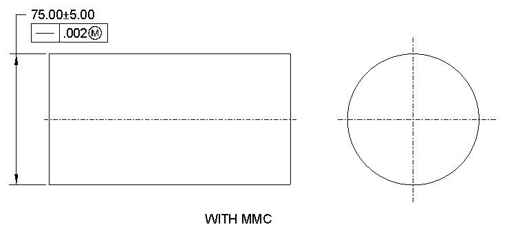
MMC Applied: Yes, Only with Axis straightness
Straightness tolerance is a 2D tolerance. It can be used on a surface to ensure that the part is uniform across the surface. Straightness tolerance can also be used on a circular object where it controls the straightness of the axis. When it controls the straightness of an axis, it is called axis straightness.
Straightness Symbol drawing call out
Flatness
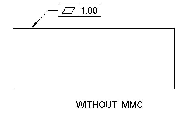
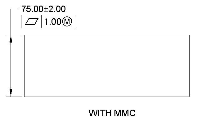
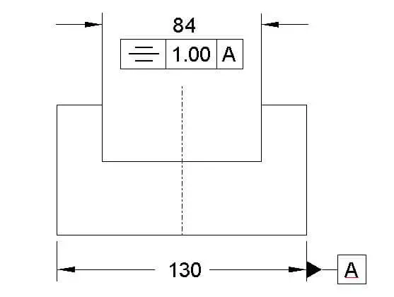
Flatness defines the tolerance zone beyond which a surface should not deviate. It clarifies how flat the surface should be. Flatness is often used to control a surface without controlling its dimension. Surface tolerance is always less than the dimension specified for that surface.
Surface tolerance zone is created by two parallel planes between which every element of the true surface should rest.
Datum Required: No
MMC Applied: Yes ( Optional)
Flatness Symbol drawing call out
Circularity
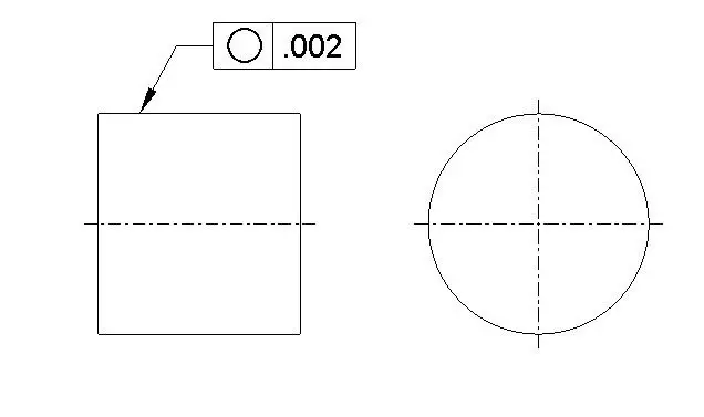
Circularity tolerance is the deviation of a circle in any cross-section of a circular object from the true circle. Circularity is often called roundness. It controls the overall form of a circular object.
Datum Required: No
MMC Applied: No
If circularity tolerance is mentioned on a circular surface, then any cross-section of that circular surface should have the same amount of circularity tolerance unless a different type of tolerances is added in addition to circularity.
Circularity Symbol drawing call out
Cylindricity
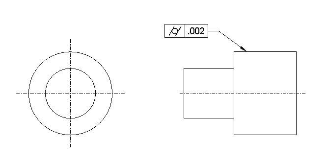
Cylindricity defines how close a cylinder surface compares to a true cylinder. It is the amount of deviation a cylindrical surface can have. It’s a 3D surface tolerance, so cylindricity applies to the whole surface instead of a circular element, as in the case of circularity.
Datum Required: No
MMC Applied: No
Cylindricity symbol drawing call out
Profile Tolerance
Ideally, profile tolerance is similar to form tolerances. But the key difference is that where form tolerance can not be used, profile tolerance can be used. Profile tolerance controls the profile of a surface(s) or curve(s).
A form tolerance is good for flat or circular surfaces. But what about irregular surfaces? How to control the shape of those irregular surfaces? That’s where profile tolerance is used.
If you want, you can use profile tolerances in flat and circular surfaces instead of profile tolerance. So basically, profile tolerance gives more freedom to control a surface.
There are two types of profile tolerances
- Profile of a line
- Profile of a surface
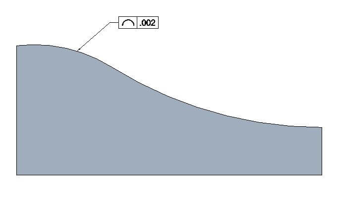
Profile of a line
A line profile is the two-dimensional version of profile tolerance, where it controls the curve elements of a surface. At any cross-section of the surface, the curve will have the same amount of tolerance as specified.
Datum Required: Optional
MMC Applied: No
Profile of a line drawing call out
Profile of a surface
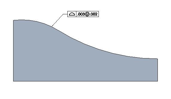
The profile of a surface is the 3D version of the profile tolerance. It controls the whole surface where the profile tolerance is specified.
Two parallel surfaces create the tolerance zone of profile tolerance, and any element of the theoretically exact surface should lie in between those two surfaces.
Datum Required: Optional
MMC Applied: No
There are different types of profile tolerance based on how it is applied to different surfaces. I would advise you to read the below article, where I explained profile tolerance in detail.
Must Read: What Is profile Tolerance
Profile of a surface drawing call out
Orientation Tolerance
Orientation Tolerance controls the orientation of a surface with respect to other surfaces. The reference object can be a surface or a reference datum.
There are three types of orientation Tolerance
- Angularity
- Perpendicularity
- Parallelism
Angularity
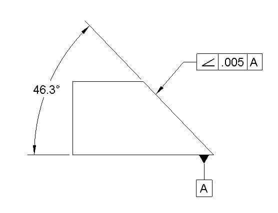
Angularity controls the orientation of a certain feature or a surface at an angle to other relative features or surfaces. The angularity can be in between 2D elements or in between 3D elements.
Datum Required: Yes
MMC Applied: Yes
Angularity Symbol drawing call out
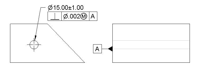
Perpendicularity
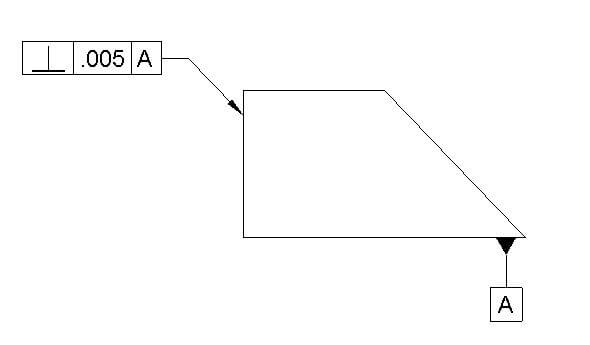
Perpendicularity defines the amount of deviation between two surfaces when theoretically, both should be perpendicular. Ideally, perpendicularity can also be defined with angularity with a 90-degree angle. But it’s an industry practice to use perpendicularity when two surfaces have a 90-degree angle between them.
Datum Required: Yes
MMC Applied: Yes
Perpendicularity can be defined on a surface or an axis. When it is placed on a surface, it is called surface perpendicularity, and when it is placed on an axis, it is called axis perpendicularity. Axis perpendicularity is useful when you want to set that axis as a datum.
Perpendicularity Symbol drawing call out
Parallelism
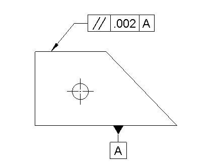
Parallelism tolerance specifies the amount of deviation a surface can have when in theoretical condition both surfaces should be in parallel to each other.
There are two types of parallelism. One is surface parallelism, and the other is axis parallelism. The surface parallelism controls the parallelism between two surfaces. In parallelism of an axis, it defines the amount of parallelism an axis should have with respect to a datum to establish itself as a datum.
Datum Required: Yes
MMC Applied: Yes
Parallelism tolerance drawing call out
Position Tolerance
Position tolerance is by far the most popular and widely used GD & T symbol. It defines the amount of deviation a feature can have from its theoretical true position.
Position tolerance is often used with MMC ( Maximum material condition) and LMC ( Least material condition) modifiers to control the position. Both MMC and LMC are a feature of size modifiers, and the position can vary based on the feature of size.
There are three types of position tolerance symbol.
- Position
- Concentrically
- Symmetry
Position
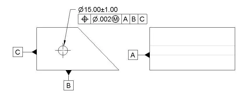
Position tolerance defines the amount of deviation of position from its true position. The true position is the theoretical exact location of a feature.
Datum Required: Yes
MMC Applied: Yes
Position tolerance drawing call out
Concentricity
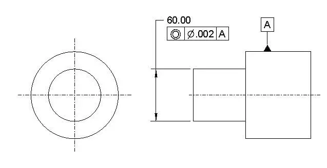
Concentricity is often called coaxiality and it is the amount of deviation an axis of a circular object can have with respect to a reference axis. Typically concentricity is a complex tolerance as you need to measure an intangible axis instead of a readily available surface.
Datum Required: Yes
MMC Applied: No
Concentricity tolerance drawing call out
Symmetry
Symmetry is a three-dimensional tolerance that defines two features on a part that are uniform across a datum plane. So ideally, both features should share the same true central datum plane. Symmetry tolerance offers the deviation from that true central datum plane.
Datum Required: Yes
MMC Applied: No
Symmetry tolerance drawing call out
Runout Tolerance
Runout is the amount of tolerance a given feature can have with respect to a datum when it is rotated at 360 degrees. Basically, it is the control of circularity with respect to a datum.
You might be confused between circularity and runout. But keep in mind that circularity is an individual form control tolerance whereas runout is a reference featured control tolerance.
There are two types of runout tolerance.
- Circular Runout
- Total Runout
Circular runout
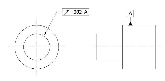
Circular runout is a two-dimensional tolerance that defines how much deviation a circular element of a surface can have with respect to a datum ( Usually an axis) when it is rotated at 360 degrees.
Datum Required: Yes
MMC Applied: No
Circular run out drawing call out
Total Runout
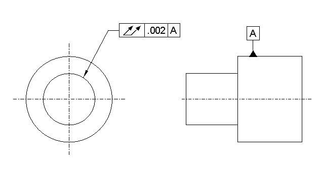
Total runout is a three-dimensional tolerance that defines how much a circular surface can deviate with respect to a datum ( usually an axis) when rotated at 360 degrees.
Datum Required: Yes
MMC Applied: No
Total run out drawing call out
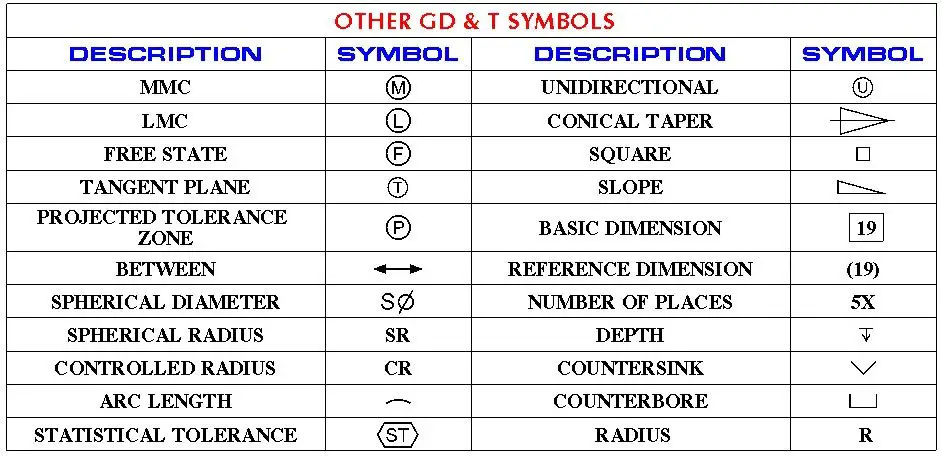
Other GD & T symbols
Here are a few other GD & T symbols that are extensively used in engineering drawings. But the list is not exclusive, and many other symbols may be used. I prefer not to include those here because those are used rarely in drawings.
Conclusion
So here it is. I have included all possible information about GD & T symbols. I know there are many other symbols used in engineering drawings. But what I included in this article are the ones mostly used. As and when you use GD & T in your drawing, you may come across different other symbols. But it is assured that if you face any issue or have any questions on GD & T symbols, I am here to help you out.
