Maximum Material Condition (MMC) And Least Material Condition (LMC) are two key elements of GD & T to leverage tolerance on critical parts. MMC and LMC offer flexibility in tolerances called Bonus Tolerance.
Many of us may not know about Maximum material calculation and least material condition calculations and what does that actually means. So let’s learn more in this article about MMC and LMC and how it affects product design.
Why MMC And LMC is important?
One of the key reason for product failure is that different part does not fit properly or I can say that different parts of a product were not designed properly to fit. MMC and LMC help to solve this problem. When you apply MMC or LMC based on the scenario, it will ensure that a part can be assembled with the mating parts even in the worst-case condition. What that means is that there will be few bad parts and a few rejections of parts. That helps in better product design.
MMC and LMC only apply to a dimension that shows the feature of size and not on any individual dimensions. So Let learns first what is a feature of size before learning about MMC & LMC.
You may also like to read: What is an orthographic projection
What Is Feature Of Size
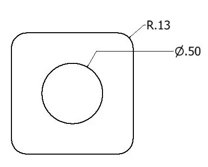
Any dimension or annotation which depicts the length, width, depth, or volume of a feature is called a feature of size. If any dimension or annotation which shows the position of a feature can not be termed as a feature of size.
Let’s take the below example, the Diameter .50 is a feature of size as its showing the features overall size but R.13 is not a feature of size.

What Is Maximum Material Condition (MMC)
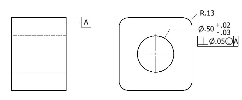
The maximum material condition is commonly called MMC. MMC is a condition of a feature when it has the maximum material. Just see the first example of the shaft. In this example, the Dimension of the shaft is Dia .50 which is the intended size of the feature.
The feature will have maximum material when the dimension is 50+.02= 50.02. In the second case, which is a hole, will attain the maximum material when the hole has the smallest size. The smallest hole has the maximum material. So maximum material condition for the hole in figure 2 would be .50-.03=.47
Maximum Material Condition Calculation
MMC of Shaft in Figure 1: .50+.02=.52
MMC of Hole in Figure 2: .50-.03=.47
Figure 1

Figure 2

MMC symbol in drawing
MMC is usually represented by capital M enclosed in a circle

Benefits of using MMC
MMC plays a big role when used with other geometric tolerances. That the reason MMC is always used with other geometric tolerances in GD & T features control frame. MMC, when used with other geometric tolerances, adds a bonus tolerance which gives leverage to suppliers for more tolerance.
When a supplier is asked for manufacturing a part with wide-open tolerance, they usually quote less price for those parts. The reason being they don’t need an expensive machine to control tight tolerance. In a nutshell, MMC in turn helps reducing part cost.
You may also like to read: First angle projection vs third angle projection
What is the least material condition ( LMC)
Least material condition is commonly termed as LMC. LMC is a material condition when a feature has the least amount of materials.
In figure 3 the least material condition for the shaft is when the dimensions is .50-.03=.47
In figure 4, the least material condition for the hole is when the hole size is having the largest diameter which is .50+.02=.52.
Least Material Condition Calculation
LMC of Shaft in Figure 1: .50-.03=.47
LMC of Hole in Figure 2: .50+.02=.52
LMC symbol in drawing
LMC is usually represented by capital letter L enclosed in a circle.

Benefit of using LMC
Like MMC, LMC also plays a big role in opening up tolerances when used with other geometric tolerances. It also adds up bonus tolerance. But the key benefit that LMC offer is protecting the least amount of material when there is a hole next to it. When a hole is very close to the edge of a feature, it may lead to failure.
Regardless of feature size ( RFS)
Regardless of feature size is commonly termed as RFS. RFS does not add up any bonus tolerance and the only tolerance available is the feature of size tolerance ( if any). So RFS is only used when the part is very precise and the application will be for critical components like in aircraft and medical devices.
Since RFS does not add any bonus tolerances so it causes more burden for the manufacturer to control the tight tolerance which eventually increases the part cost. RFS does not have any symbols. What that means is that if any feature control frame does not have any material condition symbol, RFS by default gets applied.
What is Bonus Tolerance
The whole point of reading this article will be useless if we don’t learn about bonus tolerance. As I already said, the key benefit that MMC and LMC offer is bonus tolerance.
Bonus tolerance is the additional tolerance that MMC and LMC offer apart from the feature of size tolerance ( if any). Bonus tolerance offers the flexibility to manufacturers to have a wide tolerance zone so that they don’t need to spend much for controlling tight tolerances. Let’s understand bonus tolerance using the below examples.
In figure 3, the feature control frame shows that the shaft has to be perpendicular to the datum surface A. But it has a tolerance of .05 when the shaft is produced at MMC. What that means is that the MMC is offering a bonus tolerance of .05 to the shaft size when it becomes perpendicular to datum A.
Figure 3

| Perfect shaft size | .50 |
| The maximum Material condition of the shaft | .50+.02=.52 |
| Perpendicular tolerance at MMC | .05 |
| Total Bonus tolerance | .05 |
| Total Tolerance at MMC | .02+.05=.07 |
| Maximum shaft size MMC | .50+.02+.05=.57 |
Please make a note that in figure 1, the maximum tolerance (.07) will be available when the feature is produced at MMC. If the feature is leaning towards LMC, the incremental amount of tolerance will be deducted. For example, if the shaft is produced at dia 50.01 (.50+.01), the bonus tolerance will be available is .05-.01=.04. The same rule applies to the LMC condition in figure 4 if the dimension departs from LMC to MMC
Figure 4

| Perfect hole size | .50 |
| The least Material condition of the shaft | .50+.02=.52 |
| Perpendicular tolerance at LMC | .05 |
| Total Bonus tolerance | .05 |
| Total Tolerance at LMC | .02+.05=.07 |
| Maximum hole size at LMC | .50+.02+.05=.57 |
Conclusion
It’s a must for engineers to have a good idea about the maximum material condition and least material condition. Especially for product designers, LMC and MMC are very important to have an efficient product design.
That’s all we have in this article. If I missed anything or you need any clarification on this, please do let us know in the comment section.


