First thing first, you can not simply show any GD & T without a feature control frame. The feature control frame is the medium through which you can communicate the GD&T types and values in engineering drawings. So feature control frames play a very important role in the drafting world.
What Is Feature Control Frame
The feature control frame is a symbol through which you can show GD & T in engineering drawings. Features control frame has different blocks to communicate different GD & T information. It is used to communicate simple GD&T as well as very complex GD & T annotations.
GD & T Feature control frame is used to communicate the following set of information.
- GD&T symbol
- GD&T tolerance value
- Material Modifiers
- Datum reference
Blocks Of Feature Control Frame: Feature Control Frame Symbols
These are the blocks usually shown in a typical feature control frame to communicate a different sets of information.

Leader Line (Must)
The leader line shows the applicable surface, edge, or datum where the feature control frame is applicable, or in other words, it shows the entity where the said GD&T is applicable.
Geometric Symbol (Must)
This section shows the geometric symbol that is applicable. There are 14 symbols in GD & T and details about each and every GD & T symbol are explained in this article.
Circular Tolerance Zone Symbol (Must For Position)
In Positional tolerance, you need to add a ” Diameter” symbol that indicates that it is a circular tolerance zone. In the case of other geometric tolerance types, no symbol is required.
Geometric Tolerance Value (Must)
In this section, you need to show the tolerance value for the specified geometric tolerance type. Showing the tolerance value is a must because the feature control frame does not have any sense without that.
Tolerance zone modifier / Material Modifier (Optional)
Here you have to show different material modifiers if it’s a feature of size. Like MMC, LMC, or other optional symbols. For RFS, you don’t need to show any modifier symbol.
You can also show symbols like ” Projected Tolerance Zone” if you want to extend the tolerance beyond the part boundary ( Applicable in the case of assemblies of two parts with fasteners). There can be other types of special symbols also as and when applicable.
Primary Datum ( If Applicable)
You need to show the primary datum if it is applicable. For some GD & T symbols like form tolerances ( Straightness, flatness, circularity, cylindricity), datum reference is not required. But for all other cases showing a datum is a must. This is the datum that has the highest priority and should be fixed first during the measurement.
Secondary Datum (If Applicable)
If you want to control the geometric tolerance with a secondary datum, then you can show that here. That is again optional as not all GD&T symbols require a secondary datum. Please see this guide on Datum to know how to decide on a secondary datum. The secondary datum will be fixed after the primary datum during the measurement.
Tertiary Datum (If Applicable)
Like the secondary datum, a tertiary datum is also optional and should be shown only when it is applicable. During measurement, this is the datum that will be fixed last.
What Is a composite feature control frame?
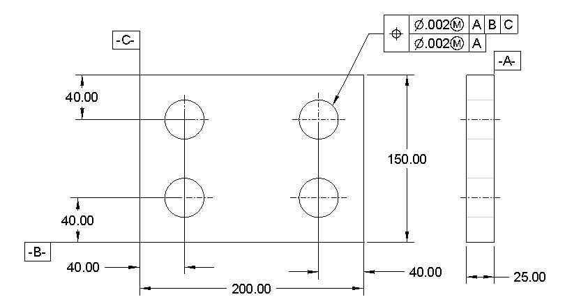
Till now, in this article, we have only seen a single feature control frame for any specified surface. But sometimes, an entity can have multiple geometric tolerances. In that case, we can show both the geometric tolerance in a single feature control frame stacked together like what is shown below. This is called a composite feature control frame.
Feature Control frame examples: How to read feature control frame?
Here is a couple of example of how feature control frames are shown on engineering drawings.
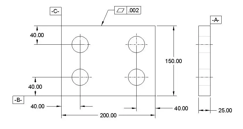
Example -1: No Datum Reference
This is an example of a simple feature control frame that has no datum reference. In this example, the feature control frame shows that the specified surface should be flat with a .002 inch tolerance.
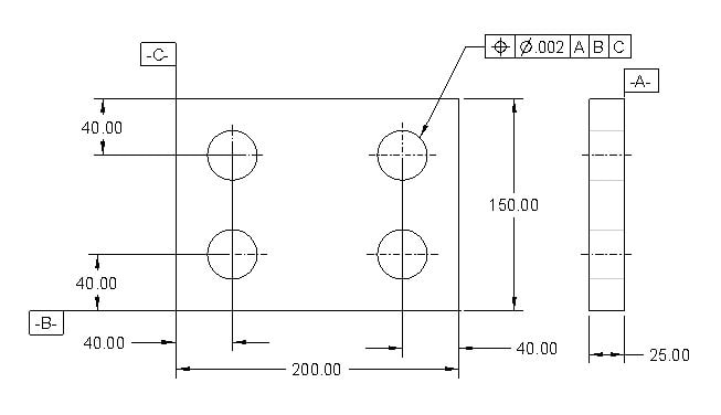
Example-2:
This is a feature control frame with center axis position tolerance with respect to datum A, B, and C. There is no modifier symbol shown next to the tolerance value, which means RFS automatically applies.
What this feature control frame symbol means is that the center axis of the specified hole can shift up to a .002 inch diameter tolerance zone with respect to datum A, B, and C.
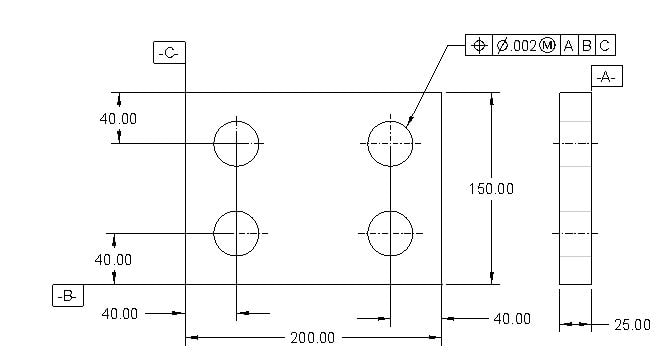
Example-3 (Bonus Tolerance): Recommended
This feature control frame is similar to the earlier one, but a material modifier ( Symbol M next to the tolerance value) is added. This means that manufacturers can have bonus tolerance if the hole size shifts from MMC to LMC. This is a recommended method as this gives manufacturers some extra tolerance. Otherwise, the part cost would be high due to tight tolerance.
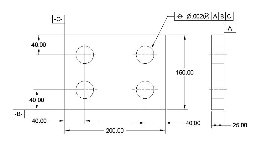
Example-4: Other Optional Symbols
Instead of a material modifier, a project tolerance symbol ( Symbol P) is shown in this example. You can use any other applicable symbol also as per ASME standards.
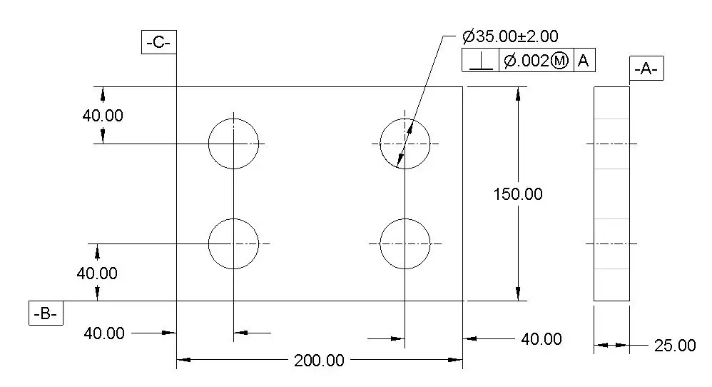
Example-5: Feature Control Frame On Feature Of Size
Here in this example, the feature control frame is attached to the feature of the size dimension. What does that mean that the feature of size has a direct impact on the applicable tolerance.
In this example, the center axis should be perpendicular with respect to datum A with a tolerance of .002 ( Circular tolerance zone) at the maximum material condition. If the diameter is shifting towards LMC, the axis will have more tolerance called bonus tolerance.
Example-6: Feature Control Frame For Establishing A Datum ( Center Axis)
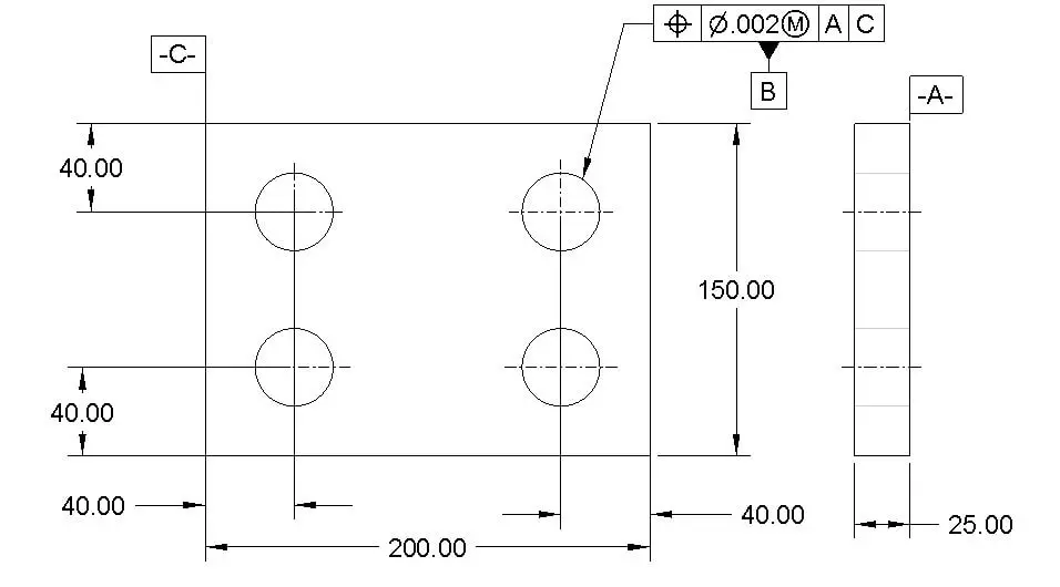
As you can see below picture that the datum B symbol is attached to the feature control frame. That means that the geometric tolerance will determine the position of Datum B. Here in this example, the datum B is the hole axis that gets a positional tolerance of .002 at MMC with respect to datum A and C. Both datum A and C are fixed but datum B is not fixed and will vary based on how the hole is produced. This feature control frame is very common across industries.
Example -7: Feature Control To Establish A Datum ( Center Plane)
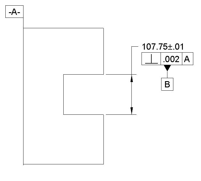
Here in this example, the center plane of the cutout is the datum B. But the central plane has a perpendicular tolerance of .002 with respect to datum A.
Example-8: Feature Control Frame For All Around Surfaces
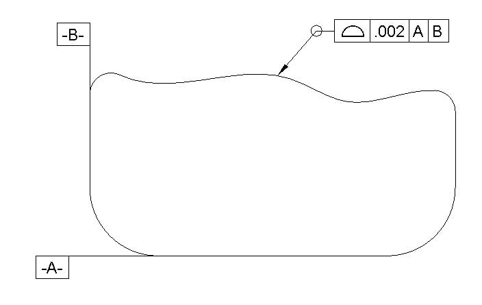
Do you see the small circle at the leader line? This is called an all-around symbol. That means that this profile tolerance is applied to the whole periphery of the geometry shown in this view. For example, if this is a front view, then all surfaces around the periphery of this figure will have the same profile tolerance applied.
Example-9: Feature Control Frame For All Surfaces
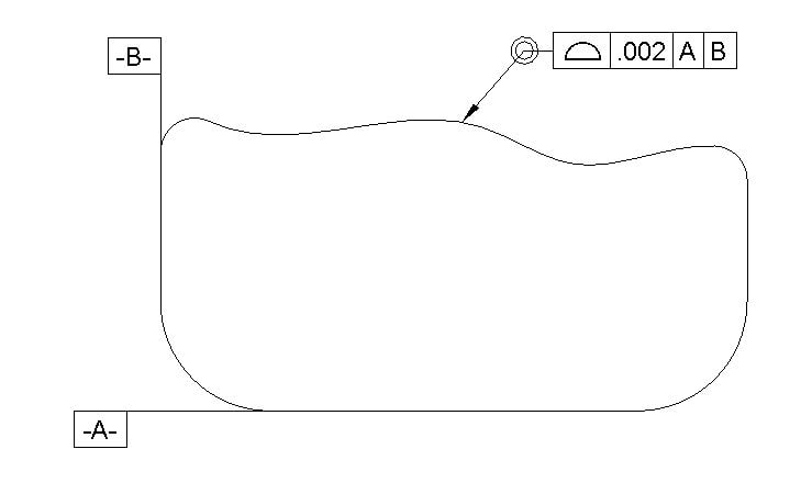
Do you see the double concentric circle at the end of the leader line? That denotes an all-surface symbol. So in this case, the profile tolerance is applied to the whole part irrespective of whether all surfaces are shown in this view or not. So all around symbol is applied for some specific set of surfaces that are tangent to each other, and all surface symbol is applied to the whole part.
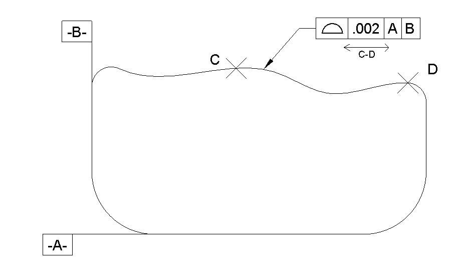
Example-10 Feature Control Frame Applicable To Certain Area Of Entities ( In Between)
In this case, the profile tolerance of .002 is only applicable on the surface between points C and D. This is really a good way of showing a geometric tolerance if you want to apply GD&T only to a specific area of a surface. With this, you can save a lot of costs for manufacturing a part. This type of tolerance is very popular in industries for reducing part cost
Conclusion: GD&T Feature Control Frame
Frankly speaking, It takes time to master GD&T. It’s really hard to learn GD&T by just reading a few articles. The feature control frame is the main element of GD&T. I tried my best to explain the feature control frame in this article with numerous examples to give you some idea of what kind of feature control frame is used in industries. I hope that helps.
If you still feel that you have some doubts or you need some support in implementing GD&T on engineering drawings, then please don’t hesitate to ask your questions in the comment section and I will be happy to assist.
Frequently Asked Question On GD&T Feature Control Frame
What is a feature control frame?
A feature control frame is the key element of GD&T to communicate geometric tolerances, tolerance value, data, and other applicable modifiers. Without a feature control frame, we can not show GD&T on engineering drawings.
Is it mandatory to show datum in the feature control frame
No, it is not mandatory. If you are showing form tolerances, then a datum reference is not required.
What are material modifiers in the feature control frame?
Material modifiers give extra tolerance to manufacturers based on how much the feature size is shifting from the specified size. For example, if a hole size is shifting by .001, then the same amount is added to the tolerance of the hole center axis if a GD&T material modifier controls that.
